
Electrical Design
Microcontroller
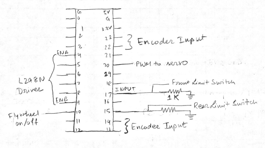
The robot, made to run autonomusly, was controlled by a Teensy LC microcontroller. The Teensy was mounted on a perma-protoboard using soldered header pins. All connections were soldered onto the perma-protoboard to ensure robustness. The Teensy was powered through the 5V Voltage Regulator that's part of the L298N Driver chip. The Teensy provided the 3.3V wherever required. The limit switches were connceted to the Teensy on the NO pin and to +3.3V on the C pin. The connections to the Teensy can be seen below.
Drivetrain Circuit
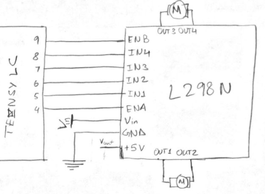
We used a L298N Full-Bridge Driver to drive our motors from the Teensy LC. The enable pins on the L298N were connected to PWM output pins on the Teensy to control speed. The battery power supply (in the figures represented by +12V) was directly fed to the L298N and the 5V output is used to power the Teensy. The batteries were connected in series to provide more power to the motors and drive faster.
We also had encoders on the robot, that ended up not being used, but the circuit is included here for completeness.
Flywheel Driver + Feeder Servo
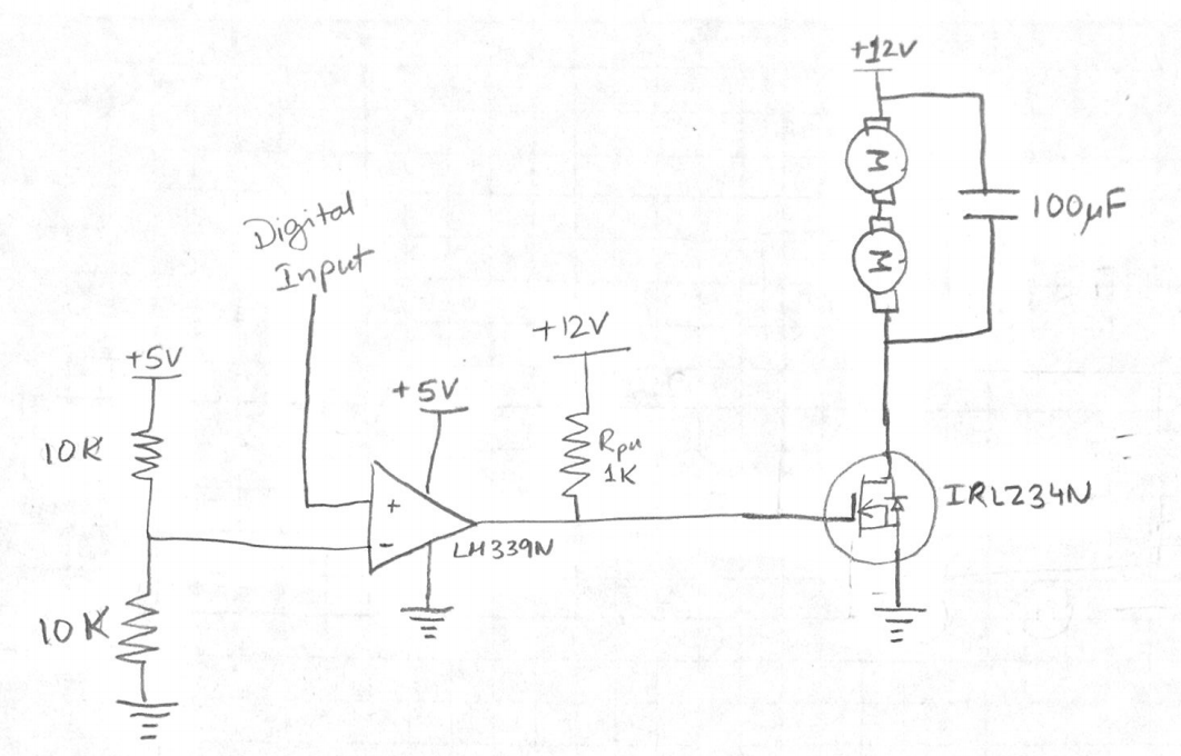
The Flywheels were driver by a power N-type MOSFET, the IRLZ34N. This MOSFET was controlled using a LM339N comparator set-up as an open-collector device; this was done to swtich the MOSFET on with higher voltages and therefore lower its resistance in the on-state. The circuit diagram can be seen here.
The fireballs were fed into the system using a servo. This servo was connected to a PWM pin on the Teensy and controlled using a library provided with the Servo. The servo was also connected to +5V and GND.